Compaq iPAQ 3650 Modifications to
Support an External Microphone

Eric Woudenberg, Speechworks Int'l
eaw@speechworks.com
This work was funded in part under the
DARPA Communicator Project,
Contract N66001-00-1-8958
This work was funded in part under the
DARPA Communicator Project,
Contract N66001-00-1-8958
These instructions give a procedure for permanently disconnecting the unit's built-in microphone and converting the existing stereo headphone jack into a combination mono-headphone / mono-microphone jack.
Slide open the small hatch cover near the DC power connector and switch the battery off. This will erase all data in the unit, so make sure you have backed up anything important.
Carefully pull the back off. The battery flex-cable will generally pop out of its plug. If it doesn't, gently lift it out.
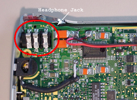
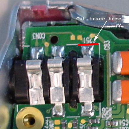
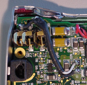
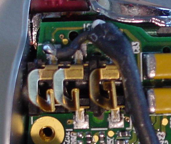
Find the circuit board trace leading to the bottom-most of the 3 headphone jack contacts and carefully cut it so that the contact is disconnected from the circuit:
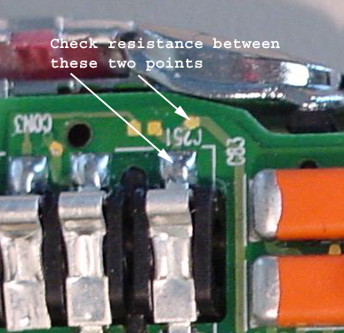
Check the resistance between the contact and the trace, it should be in excess of 1k ohms if you have successfully cut the trace:
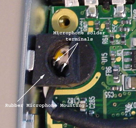
Carefully pull back the rubber boot holding the microphone to expose the terminals. Desolder the white and black wires (a third hand may be helpful here).
Carefully solder the wire you just removed onto the headphone jack. The white wire (center conductor) goes to the bottom contact (the one whose trace was cut), the black wire (outer shield) goes to the top contact (ground).
Make sure that the stylus spring, stylus latch and battery switch door are all in their correct position. Holding the back over the unit, re-attach the battery connector plug:
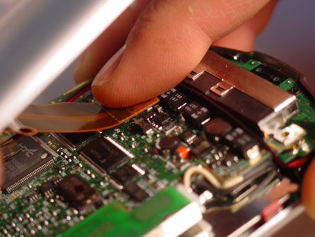
Carefully reassemble the iPAQ halves, ensuring that their tops mate properly, and dealing with the expansion sleeve connector and bottom part last. Push and snap the pieces together, working your way down. At the bottom, you may find that the expansion connector and the plastic lip on the bottom of the back hang up as you try to push the halves together. I use the stylus to reach in through the socket cutout in the case and pull the expansion connector into position. Then I use my thumb to push and force the plastic lip on the bottom of the back into its correct position.
We made a small movie of the iPAQ being closed back up (2MB).
A standard cell phone headset may be used, although the plug size is different. The iPAQ has a 1/8th" jack, cell phone headsets have a 3/32" plug. An adapter is available from Radio Shack to accomodate this difference, it adapts a 3/32" plug to a 1/8th" jack.
With the cell phone headset plugged in, you should be able to use the built-in recorder application to record and playback memos.
I have noticed that after making this change, the external speaker is quite faint. I use the headset exclusively so this is not a problem for me. I suspect that the connection between the other side of the 3rd headphone jack contact and its associated circuit must be cut in order to totally isolate the microphone circuitry from the speaker circuitry.